STRESS ANALYSIS OF AIRCRAFT METAL FUEL TANK UNDER FEDERAL AVIATION REGULATIONS –PART 23”
ABSTRACT
NAL is in the process of developing HANSA – 4 Aircraft, which is ideally suited for civil transport, aerial survey, training etc. This HANSA is designed according to Federal Aviation Regulations Part 23 (FAR-23) design document. This is a guideline for design of aircraft having a maximum takeoff weight of more than 750 kg and up to 19500 kg. The FAR-23 design document details out the loads and broad procedures for design of aircraft components like fuel tank etc.
The fuel tank designed for HANSA – 4 is made of Aluminum alloy and it can carry 100 liters of Aviation petrol having specific gravity of 0.73. In this work, stress analysis of this fuel tank under FAR loads is considered for different inertia load cases, in addition to static test pressure of 3.5 psi. (24 KPa).
Finite Element Analysis is carried out to arrive at stresses and displacements in critical components. The Analysis is carried out using ansys software finally, from the results it is concluded that the structure is safe and has adequate margin of safety in critical components of fuel tank.
MODELING AND ANALYSIS OF MOUNTING PLATE OF A ROTARY COMPRESSOR
ABSTRACT
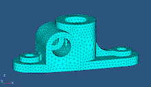
In the Tecumseh Compressors, the compressors manufactured are using mounting plates having the pitch circle diameter of 211mm. This mounting plate is welded to the compressor bottom and through the holes of this plate; the compressor gets mounted on to the A/C housing.
The vibrations from the compressor get transferred to the A/C housing there by producing noise, which is undesirable. These vibrations will be greater enough to produce noise when the natural frequencies of the compressor, the mounting plate and the A/C housing coincide resulting in resonance. To avoid this, there should be a frequency shift in either of the components. Frequency shift in Mounting Plate will give better results as that is the media of transfer of Vibrations form compressor to the A/C housing.
Under this Project, determination of the Natural frequencies of the mounting plate, amplitudes of vibration in it are studied. This determination is done using Static, Modal and Harmonic Analyses. Three models have been considered and on the existing model experiments have been carried out. The analysis results of the existing model are compared with the experimental results and validating the analysis procedure, the same analyses are carried out to the rest of the two models. Upon analysis of the three models, the better one out of them is suggested.
DESIGN AND ANALYSIS OF INJECTION MOULD FOR MINERAL WATER BOTTLE CAP
ABSTRACT
Injection molding is the most important process in the manufacturing of plastic parts. It is done by forcing melted plastic in to a mold cavity until it cools and forms a specific plastic shape. Plastic injection molding is very useful when the plastic parts that need to be produced are too complex or expensive to do by machine. With plastic injection molding, many parts can be made simultaneously (using the same mold).
The plastics used are the thermo-plastic (hdpe) as these materials soften when heated and re-harden when cooled. No chemical changes take place when the material is heated or cooled, the change being entirely physical. For this reason, the softening and re-hardening cycle can be repeated any number of times.
In this work, stress analysis of this cap cavity plate under the pressure 40 N/mm2 is considered, in addition to this thermal analysis is carried out at injection temperature 2200C and mold temperature 200C.
Cap is modeled in PRO-E and the meshing part is done in HYPER MESH 7.0 and analysis is carried out in ANYSIS 10.0. A finite element analysis is carried out to arrive at stresses, and deformation in cap cavity plate. Finally, from the results it is concluded that the structure is safe and has adequate safety in component of cap assembly.
DESIGN AND ANALYSIS OF AUTOMOTIVE TRUCK CAB SUSPENSION SYSTEM
ABSTRACT
The suspension system is used to isolate the chassis from the shock loads due to irregularities of the road surface. This must be handled without impairing the stability, steering or general handling of the vehicle. Suspension system for the cab is placed between the bottom of the truck cabin floor and chassis. The suspension system is fitted to the chassis using bolts. The loads coming from the floor and the chassis are taken by the suspension system to reduce the shocks levels to the driver in the cabin.
The model is designed in Catia V5 and meshed in Hypermesh7.0 and translated to Ansys 10.0. The model is simplified in Ansys by using the preprocessor. Constraint equations and couples are used to connect various regions of the suspension system. The loads are applied on the top flange of the suspension system.
Static analysis is made to study the deflection of the suspension system. Modal analysis is made to check the natural frequencies. Harmonic analysis is also done to plot various graphs between frequency and amplitude. Results and discussions are made from the results obtained from the Ansys and conclusions are given and scope for future work is also given.
DESIGN AND ANALYSIS OF TILTABLE TRUCK CABIN FLOOR
ABSTRACT
In the truck the floor as a load gatherer and takes the loads of the driver and co-driver loads and also the side loads and the road loads under different loading conditions. The loads from the road are transmitted to the floor through the vehicle suspension to the cabin suspension and the n to the floor
Floor is modeled in CATIA and the meshing part is done in HYPER MESH 7.0 and analysis is carried out in ANYSIS 10.0. A finite element analysis is carried out to arrive at stresses and deformation on the floor. Finally, from the results it is concluded that the structure is safe and has adequate safety.
ANALYSIS OF RESIDUAL STRESSES IN A BUTT WELD USING ANSYS SOFTWARE
ABSTRACT
Low carbon steels are prone to distortion and cracks due to residual stresses induced during welding. This project gives the information about the residual stresses induced in a butt weld joint due to welding. Experimentation was carried out on a plate made of low carbon steel having dimensions 0.115 x 0.048 x 0.006 meters. The type of welding chosen is Manual Metal Arc Welding (MMAW). Single pass welding was carried out. Experimental values calculated were taken as input for the analysis in ANSYS software.
A model was generated in ANSYS 9.0 (A general purpose FEA software) using SOLID BRICK 8 NODE 70 (3D solid element with temperature dof) and PLANE 55 (A 2D Solid Element with 4 nodes), as per the dimensions of the plate taken for the experimentation. A refined mesh is made based on the convergence criteria and the analysis is performed to estimate the temperature distribution. Firstly a transient thermal analysis was carried out by giving heat flux as the time varying input to estimate the temperature variation. The non-linear material properties are fed for the heat transfer solution. Then coupled field analysis is carried out to get the residual stresses by coupling thermal analysis to static analysis. The variation of the temperature with time, and residual stresses are obtained. The variation of these are reported and discussed.
DELAMINATION STUDIES IN FRP COMPOSITES USING 3D FINITE ELEMENT ANALYSIS
Abstract
FRP laminated composites have been extensively used in Aerospace and allied industries due to their inherent advantages over conventional materials. However these are also susceptible to damages especially under transverse loading. Failure modes of such laminated structures are different than those of conventional metallic materials. One important and unique mode of failure in such components is Delamination. Delamination is separation of adjacent plies/laminae due to existence of interlaminar stresses. This mainly occurs at free edges or around discontinuities depending upon the stacking sequence of the laminate. Once Delamination occurs, it becomes important to know whether the laminate could still be used with the existing delamination or up to what size of the Delamination the laminate could be used. So the present work aims at analyzing a laminate having Delamination to determine the severity of the existing Delamination and the propensity of the Delamination growth. 3DFE analysis along with concept of LEFM will be used the FRP laminated composites.
DESIGN AND STRUCTURAL ANALYSIS OF HIGH SPEED HELICAL GEAR USING ANSYS
ABSTRACT
Marine engines are among heavy-duty machineries, which need to be taken care of in the best way during prototype development stages. These engines are operated at very high speeds which induce large stresses and deflections in the gears as well as in other rotating components. For the safe functioning of the engine, these stresses and deflections have to be minimized.
In this project, static-structural analysis on a high speed helical gear used in marine engines, have been performed. The dimensions of the model have been arrived at by theoretical methods. The stresses generated and the deflections of the tooth have been analyzed for different materials. Finally the results obtained by theoretical analysis and Finite Element Analysis are compared to check the correctness. A conclusion has been arrived on the material which is best suited for the marine engines based on the results.
DYNAMIC ANALYSIS OF THIN –WALLED COMPOSITE I- BEAMS
ABSTRACT
In an effort to save weight while still remaining high strength, many contemporary structural systems are designed with lower margins of safety than predecessors. The criterion of minimum weight design is particularly prevalent in the design of aircraft, missile, and spacecraft vehicles. One obvious means of obtaining a high strength, minimum weight design is the use of light, thin-walled structural members of high strength alloys. Thin- walled beams of open sections such as I, Z, Channel and angle sections are frequently used for intricate structures in spacecrafts. Due to low torsional rigidity thin-walled beams of open sections, the problem of torsional vibrations and stability is of prime interest. For the last three to four decades mechanical vibrations have been recognized as a major factor in the design. Mechanical vibrations produce increased stress, energy loss and noise that should be considered in the design stages if these undesirable effects are to be avoided, or to be kept minimum.
The present work particularly deals with dynamic analysis of lengthy uniform thin-walled uniform I-beams and tapered I-beams of open sections, particularly composite beams. Fiber-reinforced plastics (FRP) have been increas¬ingly used over the past few decades in a variety of structures that require high ratio of stiffness and strength to weight. In the present thesis, the analytical model developed by Lee and Kim [11] is taken and the dynamic behavior of a thin-walled I-section composite beam is studied in detail. This model accounts for the coupling of flexural and torsional modes for arbitrary laminate stacking sequence configuration, i.e. symmetric as well as unsymmetric, and various boundary conditions are also discussed in detail. A displacement-based one-di¬mensional finite element model is developed to predict natural frequencies and corresponding vibration modes for a thin-walled composite beam. Equations of motion are derived from Hamilton's principle. Numerical results are obtained for thin-walled composite beams addressing the effects of fiber angle, modulus ratio, height-to-thickness ratio, and boundary conditions on the vibra¬tion frequencies and mode shapes of the composites. Using ANSYS 10.0, the modal and harmonic analysis are carried out and presented in graphical form.
DYNAMIC RESPONSE ANALYSIS OF A THREE WHEELER CHASSIS FRAME USING FINITE ELEMENT ANALYSIS
ABSTRACT
A three-wheeler is essentially a motion disturbance vibrating system with the ground providing input. The tyres which are in contact with the ground, convert this input displacement into a forcing function which acts on the unsprung masses, these masses are constrained by linkages so that they follow certain paths. Ride response is dependent on the ground profile, tyre and suspension characteristics, physical dimensions and the inertial properties of the sprung and unsprung masses of the vehicle.
The objective of this thesis is to analyze the dynamic behavior of vehicle using Finite Element modeling. This project also includes the response of the three wheeler chassis frame to road surface inputs and to provide the best vehicle in vibratory motions.
In Finite element modeling, analysis is done to determine the dynamic behavior of the vehicle in Harmonic and Transient excitations. Modal analysis and parametric study has also been carried out. Spectrum analysis is carried out in order to obtain the maximum stresses, as the vehicle running on the road is subjected to the random vibrations.
The results obtained from Finite element modeling in modal analysis were studied and are compared with those of rigid body modeling. In Transient analysis excitation magnitude and acceleration values at the key nodes are analyzed. From spectrum analysis maximum stress point is noted. Conclusions were derived from the study and suggestions are made to improve the performance of vehicle, thus stability is established.
FINITE ELEMENT ANALYSIS OF LPG CYLINDER
ABSTRACT
This project aims at reduction of weight of Liquid petroleum gas (LPG). So, the finite element analysis of Liquefied Petroleum Gas (LPG) cylinders made of Steel and Fiber Reinforced Plastic (FRP) composites has been carried out. Finite element analysis of composite cylinder subjected to internal pressure is performed. Layered shell element of a versatile FE analysis package ANSYS (version 9.0) has been used to model the shell with FRP composites.
A number of cases are considered to study the stresses and deformations due to pressure loading inside the cylinder. First, the results of stresses and deformation for steel cylinders are compared with the analytical solution available in literature in order to validate the model and the software. The weight savings are also presented for steel, Glass Fiber Reinforced Plastic (GFRP) composites and Carbon Fiber Reinforced Plastic (CFRP) composite LPG cylinders. Variations of stresses and deformations throughout the cylinder made of steel, GFRP and CFRP are studied.
A complex orthotropic mechanics of FRP composites has been studied and discussed in brief to have some understanding of behavior of FRP composites. In addition to that an introductory Finite Element Method has also been presented on the basis of which the cylinder has been analyzed.
FINITE ELEMENT ANALYSIS AND FATIGUE ANALYSIS OF SPUR GEAR UNDER RANDOM LOADING
ABSTRACT
The gear fitted in the gearbox Armored tracked vehicle is vulnerable to considerable fatigue damage over its life period due to the dynamic excitations caused by the terrain undulations, the rotating wheel and track assemblies. For this purpose, initially static analysis of the model was carried out to validate the model and the boundary conditions correctness. Further Modal analysis is carried out to determine the dynamic characteristics of the gear model. The random load time history is transformed in to frequency domain using Fast Fourier transform to obtain load power spectral density (PSD). Then the stress PSD response is obtained at critical node from the random vibration analysis. Once the spectrum of stress variation is obtained given input to the fatigue analysis and fatigue life is determined by FE package ANSYS 9.0.
FINITE ELEMENT ANALYSIS OF A GAS TURBINE ROTOR BLADE
ABSTRACT
In the present work the first stage rotor blade of a two-stage gas turbine has been analyzed for structural, thermal using ANSYS 9.0, which is a powerful Finite Element Software. In the process of getting the thermal stresses, the temperature distribution in the rotor blade has been evaluated using this software.
The design features of the turbine segment of the gas turbine have been taken from the preliminary design of a power turbine for maximization of an existing turbojet engine. It was observed that in the above design, the rotor blades after being designed were analyzed only for the mechanical stresses but no evaluation of thermal stress was carried out. As the temperature has a significant effect on the overall stress on the rotor blades, it has been felt that a detail study can be carried out on the temperature effects to have a clear understanding of the combined mechanical and thermal stresses.
In the present work, the first stage rotor blade of the gas turbine has been analyzed using ANSYS 9.0 for the mechanical and radial elongations resulting from the tangential, axial and centrifugal forces. The gas forces namely tangential, axial were determined by constructing velocity triangles at inlet and exist of rotor blades. The rotor blade was then analyzed using ANSYS 9.0 for the temperature distribution. For obtaining temperature distribution, the convective heat transfer coefficients on the blade surface exposed to the gas have to feed to the software. The convective heat transfer coefficients were calculated using the heat transfer empirical relations taken from the heat transfer design dada book. After containing the temperature distribution, the rotor blade was then analyzed using ANSYS 9.0 for the combined mechanical and thermal stresses. The radial elongations in the blade were also evaluated.
The material of the blade was specified as N155 but its properties were not given. This material is an iron based super alloy and structural and thermal properties at gas room and room temperatures were taken from the design data books that were available in the library of BHEL(R & D), Hyderabad.
The turbine blade along with the groove is considered for the static, thermal, modal analysis. The blade is modeled with the 3D-Solid Brick element. The geometric model of the blade profile is generated with splines and extruded to get a solid model.
The first stage rotor blade of a two-stage gas turbine has been analyzed for structural, thermal using ANSYS 9.0 Finite Element Analysis software. The thermal boundary conditions such as convection and operating temperatures on the rotor blade are applied on theoretical modeling. Analytical approach is used to estimate the tangential, radial and centrifugal forces
.
FINITE ELEMENT MODELING AND STATIC ANALYSIS OF OPEN TOWER
ABSTRACT
Open towers are one among the different types of towers used for the purpose of signal transmission. They are telescopic in nature and are designed in a special manner, which makes the whole structure portable by converting in to a single unit. It consists of main pipe and four supporting members. In order to reduce the weight of the structure it is fabricated with fiber reinforced plastics (FRP). The main pipe is a combination of several sections, which slide into the main member with the help of rollers to form a single unit. The four supporting members can be made integral with the main pipe with the help of a movable flange which slides on the main member.
Subscribe to:
Post Comments (Atom)

No comments:
Post a Comment